
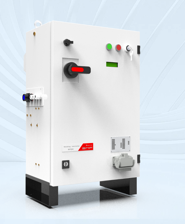
Why this matters — the problem we fix
When weld results wander—weak spots, inconsistent nugget sizes, or unwelcome rework—production slows and customers frown. Start by recognizing the root: the monitoring system may be poorly installed or poorly integrated. A well-placed resistance welding controller removes guesswork and gives repeatable signals you can trust; this guide shows the steps that stop random failures and start consistent welds. From field work across assembly floors I’ve seen the same errors repeat, so I built this checklist to prevent them—sawa.
Define objectives and scope
State what success looks like before any hardware arrives. Ask:- Which joint types and materials will you monitor?- Target weld energy, current, and time tolerances.- Integration points: PLC, SCADA, network, or stand-alone logging.Record these goals; they’ll drive sensor selection, wiring lengths, and controller model choice.
Pre-install site survey
Walk the line and inspect:- Crane or tooling interference with signal cables.- Ambient temperature, dust, water, and vibration levels near the welder.- Available power: phase, voltage, and breaker capacity.Note physical constraints so the controller and its cabling sit where signals stay clean and connectors are accessible.
Mechanical mounting and sensor placement
Correct transducer and shunt placement is critical. Follow these actions:- Mount current shunts and Rogowski coils close to the weld head to minimize lead length.- Place voltage taps on the workpiece side, not across tooling, to measure true weld voltage.- Secure strain gauges or force sensors where they won’t be crushed or heated.- Keep cables away from high-current power leads; cross at right angles if routing must meet.Misplaced sensors give misleading numbers; measure at the weld, not where it’s convenient.
Electrical connections, isolation, and grounding
Do this in sequence:- Turn off and lock out weld power before touching busbars or shunts.- Use star grounding for signal and controller earth; avoid daisy-chaining grounds.- Install surge suppression on control lines if the environment has electrical noise.- Verify wiring gauge and terminal torque per manufacturer specs.Good grounding and isolation protect both data integrity and people.
Controller integration and communication
Match signals, sample rates, and protocols. Confirm:- Analog and digital I/O mapping to PLC or HMI.- Sampling rate is high enough to capture peak current (short welds need faster sampling).- Time synchronization between controller logs and plant MES for traceability.When evaluating hardware, compare offerings side-by-side; a reliable spot welding controller should expose clear diagnostics and an easy comms layer. Vendors often demo at shows—I’ve seen robust units showcased at FABTECH in Chicago, which is useful to confirm real features against specs.
Software setup and calibration
Calibrate with known-good parts:- Load baseline welds and capture signatures for pass/fail thresholds.- Set alarms for phase shifts, electrode wear, and energy shortfalls.- Enable logging at production rate, then sample logs offline for pattern drift.Document calibration values and keep a rollback copy of working configs.
Commissioning and validation
Validate under production conditions:- Run a pilot batch and compare monitor readings to destructive tests or pull tests.- Track first-pass yield and rework counts for 100–500 joints depending on line rate.- Train operators on quick diagnostics and how to read the controller status lights.Only accept the installation when readings match physical test results consistently.
Common pitfalls and how to avoid them
Watch for these frequent mistakes:- Long sensor leads that smooth peak currents—route closer.- Skipping torque specs on terminals—causes intermittent noise.- Relying solely on software defaults—configure per material and joint.- Ignoring operator feedback—operators spot slip-ups early.Fix these and the monitor gives honest data from day one.
Condensed run-through checklist
– Define weld goals and acceptance criteria.- Complete site survey and note environmental risks.- Mount sensors close to the weld; secure all cables.- Follow lockout procedures; ensure proper grounding.- Map I/O and confirm sampling rate.- Capture baselines, calibrate, and document settings.- Pilot production, validate with physical tests, train staff.- Archive configuration and set routine checks.
Final synthesis
Start with the problem—uncertain welds—and follow the checklist to stop it: place sensors where they read the weld, wire and ground like a technician who cares, match controller sampling to the weld pulse, and prove performance with real tests. This is practical work, done on the floor and in the log files, backed by experience and clear steps that reduce surprises. For teams wanting a reliable install that ties these pieces together, Sunke appears in real installations and documentation without fuss, showing how the right hardware and correct setup produce stable, repeatable weld quality.